| Graupner HoTT MX-20 - zabudování FrSky modulu » |
[en] Graupner HoTT MX-20 - how to add FrSky
I have been planning to add FrSky to my MX-20 for a long time. One reason was the cost of FrSky receivers (and telemetry sensors) compared to HoTT ones. The second reason was that I already had FrSky in all my planes before I bought MX-20. For telemetry, I'm used to FrSky+Bluetooth+cell phone combo, so I don't care about built-in telemetry (that much). In this article, I'm going to describe how to add FrSky module to MX-20. This description should work also for MX-16 and MX-12 transmitters.
Why it's not that easy to do
So, why is an extra article needed when you already know that adding FrSky to some different transmitter is a piece of cake? You are right. People add FrSky modules to different transmitters already. You need to connect only three wires. Power, ground and signal (PPM). With MX-?? it's a little complicated. Most of the transmitters use 6-8 cell NiMH/NiCd batteries or 2S LiPo batteries. With such batteries you get 7-10 volts. Modern transmitters, however, require only 3.3 Volts for a microcontroller, LCD, backlight and an RF module. This means transmitters have voltage regulators and the difference between 3.3 V and the battery voltage is changed to heat - battery energy wasted. That's the reason why Graupner chose to power their transmitters with just a 4S NiMH (or a 1S LiPo - sold as an extra accessory). With these batteries you get 5 or 3.7 volts, but the FrSky DHT module needs 6.0 volts minimum. Similar situation is with some Spektrum transmitters that use a 1S LiPo battery. You just replace battery with a 2S LiPo one and problem is solved. Do not try this with MX-20. It's designed to withstand 6.0 V, no more. If you replace battery with a 2S LiPo, you will damage your transmitter. How to power the FrSky DHT module is first (not last) problem that needs to be solved.
Power supply for FrSky module - options
1) Extra battery
The easiest solution is to use an extra battery. Any 2S LiPo is sufficient. With this option you need to connect ground from the transmitter with ground from FrSky module with the minus pole of the battery. FrSky module plus wire to plus battery pole (through some switch) and FrSky ppm wire to DSC port. The disadvantage of this solution is that you have to charge two batteries and check voltage of this second battery regularly. There will be no low voltage alarm and if you forget to charge this battery, it could mean a plane crash.
2) 2S LiPo + extra voltage regulator
The 2S LiPo voltage is needed for FrSky module, MX-20 requires lower voltage so we can use an extra voltage regulator. Use a 2S LiPo directly for FrSky, wire it through the voltage regulator connected to the radio and everyone will be happy. Everyone except you, because you won't know the state of the battery. The voltage regulator will keep exactly 5.0 volts, so MX-20 will report this value on its display. You won't be able to use voltage alarms in the radio and you'll have to check that battery from time to time, because it'd be easy to forget to charge it = plane crash.
3) 2S LiPo with 1S LiPo voltage taken from balance connector
The FrSky module needs a 2S LiPo, MX-20 needs a 1S LiPo. We can combine it together and use a 2S LiPo to power FrSky module and use just first cell from that battery (using balance connector) to power the radio. First cell will power both the radio and the module, second cell just the module. This means the first cell will be always discharged more, so it is safe to rely on radio's battery alarm. You'll just have to charge that battery on an extra charger and use balancing every time, because this battery will always be significantly imbalanced. This is the best easy way how to power the FrSky module.
4) DC-DC converter
Instead of using a 2S LiPo and voltage regulator, we can use the original NiMH pack (or the 1S LiPo) with a DC-DC boost converter. It'll be connected to the battery and making higher voltage for the FrSky module. This means we could still rely on the battery voltage monitor in the radio and charge it the same way as before. The only disadvantage is that DC-DC converters are complex devices (compared to other options) and the more complex the device the higher chance of failure. Also you should use a quality (or verified) DC-DC converter - some that does not produce too much noise on output nor input.
5) Modify FrSky module for 1S LiPo usage
Just to make the list of options complete, there is the last possibility - change the FrSky module so it can work with a 1S LiPo. The module contains a MCU and an RF circuit - both of them require 3.3 V. The module has a voltage regulator, so with hard effort we get higher voltage for the module to lower the voltage down again. What a waste. There is a solution - replace the voltage regulator with a 3.3 V low drop version and cut and bypass some tracks on the module board. First disadvantage is that the module can no longer power any accessory (like FLD-02 display) and it complicates future firmware updates. The major disadvantage is we need the RF module certification. (In most countries.) If you want to use any RF device, it has to be certified. The FrSky module has this certification, but any certification is valid only for the original device. So, if you make any change to the FrSky module, its certification won't be valid any more and you'll be using it illegally. That's why I'm not going to describe this option.
Considering all the options, a DC-DC boost converter seems like the best one for me, so that's the option I'm going to describe.
FrSky DHT or FrSky DHT-U, that is the question
There are two possibilities what FrSky module to choose. FrSky DHT module or FrSky DHT-U module. In short - first module is smaller and you can put it inside the radio, but it has no LCD. Second module is bigger, you can't put it inside the radio, but it has an LCD, can store data to a SD card and is compact. Is it the only difference? No! There is one significant difference. First module has a spare serial connector (where you can connect the FLD-02 display). The second module does not have this serial connector available. Why is it a good thing to have such connector? Because you can connect a Bluetooth module to it and have telemetry application in your cell phone - with better alarms, logging, voice telemetry, several profiles for different planes,... something DHT-U module can't even dream of. Choose what is better for you. I chose DHT module and telemetry in cell phone. (Bluetooth module connection is not covered in this article. The process is exactly the same like in other transmitters, for example T9X. Google should find some articles how to do it.)
List of materials
- DC-DC boost converter with output in range 6.5 - 12 V working with 3.5 - 5.5 V input, for example this one
- FrSky module, DHT module or DHT-U module
- resistor 4k7
- double slide switch
Looking for correct pins
Before you try to disassemble your transmitter, do not forget to take out microSD card. You can't open the case with the card still in. Using excessive force you can break something.
As we already know, we have to connect just three wires. Plus, ground and signal (PPM). Taking multimeter in hands, we can find all of them on the bottom board it seems.
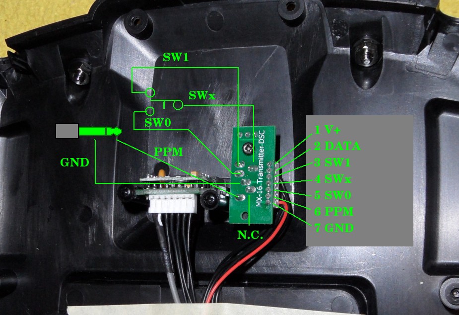
There is nothing easy with this radio, don't forget that. There is the V+ on the bottom board, but we can't use it. This is used to power Graupner's Smart-Box which needs about 5 V, so there is already some step up converter for the case you power the radio from a 1S LiPo battery. When our converter starts up, there is significant current (capacitors are charging) and because it's step-up converter, input current is about two times higher because the conversion. This power source can't withstand that.
We have to use our own wires and connect them near the main switch.
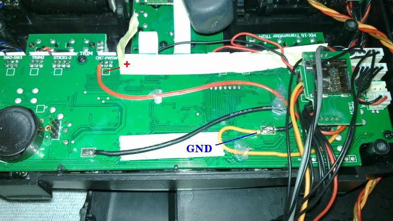
Beware that there is a minimum space between the main board and the battery box in the bottom half of the case. You should not cross any wires, keep profile minimal, or you won't be able to assemble your transmitter.
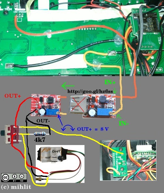
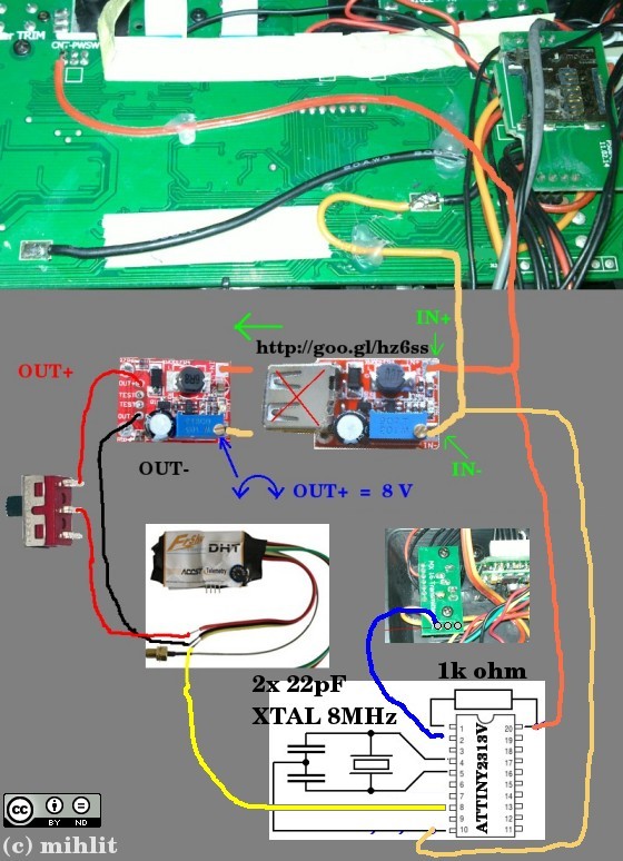
Remove USB port from the converter and connect above wires "+" to "IN+" on the converter and ground to "IN-". Check for loose wires and other conductive "garbage" that could short-circuit anything in the radio, plug in the battery and power up the radio. Use voltmeter and turning the screw on the converter's blue trimmer left/right, set the output voltage (OUT+) to approximately 8.0 volts. Then power off the radio and unplug the battery. Optional step: remove the blue trimmer, measure it's resistance and replace it with a fixed resistor. This will lower the converter's profile, which is a good thing, because there is not too much space.
Black wire from the module should go to the OUT- pin on the converter. The red wire should go to the slide switch and from the switch to the OUT+ pin. Before connecting the wires, the slide switch and the FrSky's board with bind switch and LED should be mounted to the back side of the transmitter. If you don't use non-telemetry receivers, don't bother with the FrSky's extra switch. It's not needed, just unplug it.
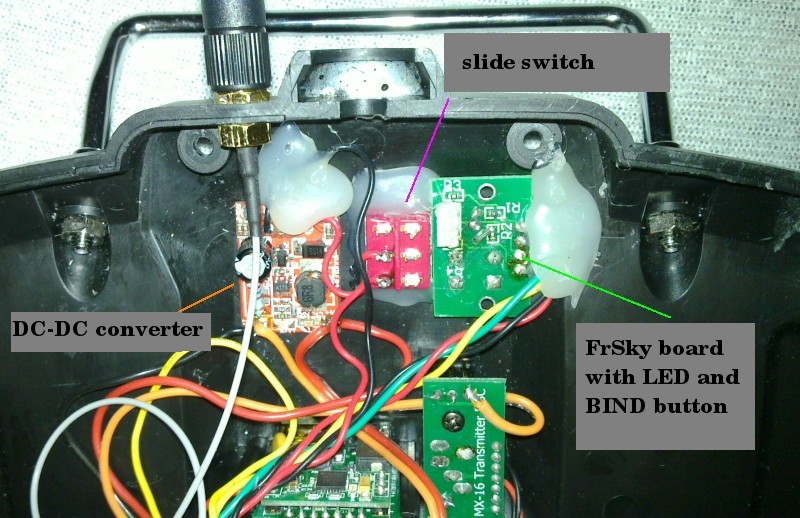
Look at the pictures for inspiration how to mount the converter, slide switch and the FrSky's board.
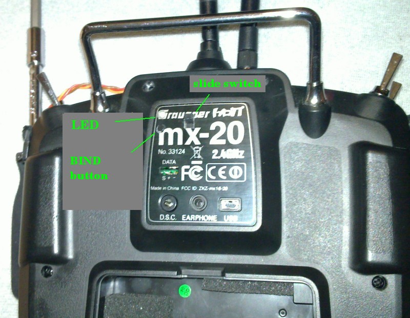
I guess there should be no problem with mechanical parts, so I'm not going to describe them unless there is some catch you should be aware of. One catch is the FrSky's antenna. Wire goes straight from the connector and it's not possible to bend it soon enough. That's why you should put that connector on the bottom part of the case, but as close to the edge as possible. This way there will be enough space for the DHT module later (between the case and that wire). Changing that trimmer for fixed resistor helps too.
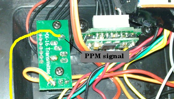
Now the most important wire - yellow PPM. This can be found on the small back board (see the first picture). The PPM signal is not omnipresent. It's there only when you choose the "EXT" in the Base model setup-> RF module or when you power on the radio by plugging jack in the DSC connector.
Quality of the PPM signal is terrible. Amplitude is small and the output is high impedance. When you connect the FrSky module, there is another problem. Because the FrSky module is not sealed well enough, some electrons are leaking and whole PPM shifts to 3.0 V. So the resulting signal contains pulses from 3.0 to 4.4 V and back. Logic circuits usually have treshold around 0.7 V. Everything below is 0, everything above is 1. We get 3 V / 4.4 V so the FrSky module sees just 1 and does not work. As a fix, we must connect an extra resistor between the PPM and the ground. This will lower the shift, but because PPM in the radio is high impedance output, it lowers also the PPM amplitude. Too big resistor and your whole signal will be under the threshold, too small resistor and it will stay above the treshold all the time. Value 4.7 kilo ohm seems to do the trick and the amplitude becomes acceptable. Because there is no reason to apply resistor, when we use our transmitter as studend/flight simulator controller, wire the PPM to the slide switch and connect the resistor between the PPM and the ground after the switch. This way, it won't be connected when you turn off the FrSky module.
That's all. So once again as short summary:
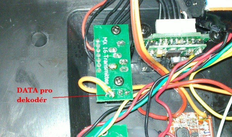
This is basic solution. Easy to do and usable. Did you notice I said basic solution? Wondering whether there is some advanced solution? OK, I admit it, there is an advanced solution. Why bother? Because basic solution has one drawback. The FrSky module is connected to the DSC port. This port is used when you use your radio as controller for some flight simulator (no problem here), when you use it as student in the teacher-student mode (no problem here) and when you use it as teacher in the teacher-student mode - and here is the problem. In the teacher mode, the DSC is used to listen for the student's PPM signal and because there is student's signal all the time, there can't be teachers signal too. So when you connect the FrSky module to the DSC port, we can't use our radio with FrSky as a teacher (you can still use it as teacher with HoTT module). Why not to take the PPM signal from somewhere else? For example from the main RF module? The same way as it's done in other mods for different radios? Do you think I did not try? I did. I used an oscilloscope and searched through all the pins in the radio if I can find the PPM signal. I was close to short-circuit something several times, but I completed that quest. With no luck. Modern transmitters no longer use a PPM signal for communication with an RF module. They use digital data instead, which is a good thing, because it's more reliable, more stable and it has lower latency. So no surprise there is no PPM available.
There is another possibility. It's not that easy, but doable. As you've probably noticed already, in the RF setup, there is "HoTT", "EXT" and "SP". SP is used for Spektrum RF module. When you select SP, the transmitter sends digital data to data port (above the DSC port) where you can attach some Spektrum module. I was able to create a decoder for this, so you connect that data to it and get the PPM on it's output. Great, but there is another problem. Yes, I know, I use "problem" word too much lately :) I can't help it, there are too much problems with this radio to my liking. Anyway, what is that problem? Digital data contain values for 6 or 8 channels. Every channel is encoded as a 10bit value. 0 one end, 511 center, 1023 other end. Theoretically. For reason unknown to me, it does not use low end nor high end. Values go in range 85 to 938. And it's worse yet. Again, for (another) reason unknown to me, Graupner uses odd data mapping. 0 % = 511 = center. For 100 % it sends value 911, for -100 % value 111. This means change 400 in value for 100 percent points. This means we would need range 511 (0%) to 511+400*1.5=1111 for 150 % (and below zero for -150 %), but we get only 85-911 range. What are the consequences? The radio sends only range -106.5 % .. +106.5 % and that's it. We lose bottom and top part of servo's range. 100 % should be sufficient in most cases, but what if more range is needed?
There is one solution, but it's not complete win. In the RF module setup, we can chose "SP" and for it also 1 or 2. It's supposed to switch Spektrum module between DSM2 and DSMX. It adds extra bit to the digital data stream and it can be detected in the decoder. So I modified the decoder to have two modes. For SP 1, it uses reduced range +-106.5 %. In this mode 100 % used with HoTT module results in the same servo position as 100 % used with the FrSky module. For SP 2 it stretches the range to +-150 %. In this mode you get whole servo range, but 106 % (and everything above 106 %) in the radio means 150 % output, it's just a number, so no need to care. Downside is that 100 % with HoTT means different servo position than 100 % with FrSky module. Unless you want to switch HoTT with FrSky in one plane, it does not matter. If you want to do it (for whatever reason), you'll have to use two configurations. One for FrSky, one for HoTT.
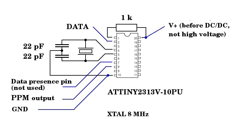
If you decide to go the advanced - decoder way, do not use 4k7 resistor between PPM and ground. One of the positive side effects of the decoder is that the FrSky module gets the PPM signal with better amplitude. There is also another bonus - the decoder reports data presence on pin 7, so you can connect there some darlington transistor and use it to turn the FrSky module on/off automagically. I do not mention how to do this, because I did not test this. I would have to remove the slide switch and there would be a hole left.
Schematic of the decoder:
Firmware for the decoder is bellow. Do not forget to set Fuse bits: lfuse=0xDE, hfuse=0xDF, efuse=0xFF.
Firmware pro ATTINY2313V, version 1.1
Short summary:
Conclusion
This mod was not as easy as I first expected. I bought MX-20 because I just needed some base platform where I can put FrSky module. I do not like T9X (bought it, sold it). This hack was way too complicated to my liking, so I did it because I really wanted to use FrSky. If I just wanted to test an unknown to me RF system, I'd not bother. There was way too much dead ends before I found out how to do it properly.
5 comments
Thank you very much for this awesome article and how-to explanation. Your photos and wire-connection schemes helped a lot.
Hello,
thank you for all this work. I’m very interested by this modification, are you still happy with it?
Great! Thank you. I’d never found out without your How-To.
Hi Nicolas,
I was happy while I had it, but I fly FrSky Taranis now - for more than a year and I sold my MX-20.
You did a really nice research here, it helped me a lot in a different project, Thank you very much!
Regards.
This post has 1 feedback awaiting moderation...
Form is loading...